
The construction of the Spire in Edgeworthstown
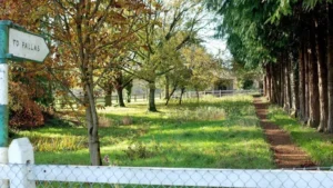
Richard Lovell Edgeworth erected a pre-fabricated spire on the Church of St John in 1811 – it lasted until the early twentieth century when it had to be removed for safety reasons. He worte a description of how the Spire was constructed and raised into place in a letter written to Nicholson’s Journal of Natural Philosophy in 1811. Below is a reproduction of the letter as well as the plans and a photo of the spire taken in 1890
Spire Construction – Richard Lovell Edgeworth from Nicholson’s Journal December 1811
Description of a Spire of a new Construction, at Edgeworthstown, combining the Advantages of Cheapness, Elegance, and Durability. In a Letter from RICHARD LovELL EDGEwoRTK, Esq., F. R.S. M. R. I.A. &c.
To W. NICHOLSON, Esq.
Edgeworthstown, Ireland, Sept. the 22nd, 1811
SIR,.
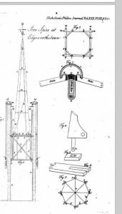
I have lately erected a spire of a new construction on the tower of the church of Edgeworthstown, and, as the attempt has succeeded, I hope an account of it will be acceptable to your readers. My object was to lessen the expense, and to facilitate the means of ornamenting places of public worship. This spire is fifty feet high from the base to the star by Height of the which it is crowned. See Plate VII, fig. 1, which is a section of the tower, the spire, and part of the machinery. The spire was made withinside of the tower, and, when completely finished, was drawn up in a few minutes by machinery, and placed on the tower, where it now stands. It consists of a skeleton of hamuered English iron, covered with with strong Welsh slates, capped where they meet on the skeleton by large copper beading, which, with the slates, is fastened to the skeleton by copper bands and cramps. The whole is well painted, and covered with sand, so as to imitate stone.
The skeleton was formed of eight bars of iron, 45 feet long, 2inches and broad, and of an inch thick. These dimensions were chosen because they are those of common bars, that are sold by ironmongers. These bars are usually
14 or fifteen feet long, and I had them welded in a common forge to the length that was requisite. Eight of these were disposed octagonally upon a base, fig. 3, about 9 feet in diameter, which is nearly the diameter of the tower. It was made of bar iron an inch square.
Before the spire was put together in the tower, the parts were previously fitted on the ground, not perpendicularly, but lyiug sideways, so that each bar could be easily reached by the workmen. With this view I took advantage of a saw pit, which permitted half the base to lie below the ground, while the apex, or point of the spire, was supported by a bench, on the surface of the ground. This enabled me to assemble and fit the bars which were necessary for cross braces, and to combine the bars accurately round the spindle of the weathercock, and to secure them by a ring of iron. The base above mentioned, fig. 3, consisted of four bars of iron, flattened where they crossed each other, with a hole through the middle of each, that received a bolt to bind them together. The ends of each of these bars, were so formed, with cheeks, as to permit the bars, that composed the spire, to lodge within them, and to be fastened to them by screw bolts. Light flat bars d, d, d, held by the same screw bolts, were placed between the bars of the spire, to keep them at due distances from each other, thus forming a species of diaphragm, fig. 3, where A represents the diaphragm resembling the rudiments of a spider’s web, c c,c, &c. the cheeks of each transverse bar of the diaphragm, and b b. b the bolts, which connect them with the legs of the spire. Beside these diametrical supports there are four bars, BB, fig. 6, 20 feet long, placed obliquely from the bottom of one bar to the opposite bar, to which they are connected by screw bolts, thus forming angular braces. The spindle of the weathercock rises 5 feet above the apex of the spire, and, passing downward through the junction of the bars, it is inserted into a solid diaphragm under and against which it is keyed by a forelock. Beside this diaphragm, and that which forms the base of the spire, there are three others DD D, fig. 6, of a construction similar to that of the lowest diaphragm, placed at equal distances fron each other. It is to be observed, that the cheeks or ends of the three upper diaphragms project beyond the upright legs of the spire, to assist in supporting the slates; but the cheeks of the lower diaphragm take in not more than two inches of the feet of the bars of the spire; which feet, as may be seen at fig. 4, are considerably broader than the rest of the bars.
At B, fig. 4, a tenon is formed at the heel of the foot of each bar, which is to receive a key, or forelock, to fasten the bar spire to the tower, after it has been raised to its place. To raise and guide this spire, a pedestal, the plan and section of which are seen at fig. 2, and 6, was constructed. Its consists of a top and base, each formed of four pieces of spire. deal 6 inches square, and of eight jambs, or uprights, of the same breadth and thickness, and 10 feet high, morticed into the base and top, so as to stand nearly under the eight legs of the spire when it is raised upon it. See fig. 6, where J JJ show the position of these uprights. The uprights are strengthened by braces, o b bo, so as to prevent them from racking, or moving obliquely. The pedestal was furnished with eight wheels 6 inches in diameter, at its upper corners; and with eight similar wheels at its lower corners; – as in the plan, fig. 2, and in the section, fig. 6, w, w.
To facilitate and guide the movement of this pedestal upwards, the tower was lined at each corner with thin planks, – PP, fig. 1, fastened to the walls perpendicularly, and adjusted with care. Against these planks the wheels of the peit destal noved upwards with little friction, keeping the spire perpendicular in its ascent.
When this pedestal was adjusted, the skeleton, which had been fitted on the ground, was taken to pieces.
The base, or lower diaphragm, upon which the bars had been adjusted, was placed and fastened in a temporary manner on the pedestal. The long bars were drawn up, one by one, into the tower above the platform; and their feet were inserted into the cheeks of the base, or lower diaphragm; where they were secured by bolts, as before described. The other diaphragms, and the iron cross braces, were then inserted between the iron bars, and firmly bolted to them. By the favour of Messrs. Worthington and Co. of Penslates, Penrhyn, I was furnished with excellent slates of dimensions sufficiently large to cover the spaces between the bars, which at the base were nearly 4 feet wide. The slates were 2 feet 6 inches high, and nearly an inch thick.* These slates were sawed to fit upon the ribs where they met, and they were rabbeted with the saw and chissel to lap over each other, so as to keep out water. They were so well joined by these means as to present one even surface, on which the courses of the slates scarcely appeared through the paint. These joints might by additional paint have been entirely concealed, but their appearance was thought to be advantageous, as it gave an idea of solidity, from its nearer resemblance to stone.
It remains to show how the slates were fastened to the iron upon which they were placed. For this purpose grooves about one quarter of an inch deep were sawed in the upper surface of each slate, parallel to the bars, and at the distance of nearly two inches from them. A copper capping, nearly semicircular, and about four inches in diameter, was placed so as to cover the joints of the slates, where they met the the bars, sinking into the grooves which were just sufficiently wide to receive the copper. The copper by its shape and elasticity caught in the grooves, so as to form, when painted, a covering perfectly impervious to rain and snow.
To fasten these copper caps and the slates to the skeleton of the spire, a contrivance was adopted, which requires some detail to become intelligible. The general idea was to fasten the capping and the slates from within, so as to leave no holes to be stopped on the outside by putty or paint. Fig. 7 is a section of the slates on a larger scale than that of the spire, where they join on the rib; of the copper capping; and of a collar, or band, by which they are connected with an iron cramp, that passes round the inside of the rib, and, hooking into the collar or band, is wedged within, against the inside of the rib. In looking at this section, care must be taken to distinguish the circular edge of the copper capping from the edge of the band or collar. The band, as may be seen in the drawing, is twice as thick as the capping. In this section of all these parts, as connected together, C is the copper capping; SS, the band or collar; H H, the cramp, or holdfast; and W, the wedge. The whole of this apparatus for fastening the slates succeeded to my wishes: it was easily executed by common workmen; the parts were easily put together; and, when adapted to their several places, they held the slates and their capping firmly upon the bars, at the same time producing a very good effect by raising a bold and ornamental moulding, or torus, fig. 7, on every angle of the spire. It is scarcely necessary to add, that part of the lower corner of each slate was cut away at A to permit the cramps to pass through, and to embrace the iron rib; and that the ends of the diaphragms were permitted to extend beyond the outward surface of the ribs, to support the perpendicular pressure of the slates. Such slates as were not thus supported rested upon the rabbets of those that were beneath them. The machinery, by which the spire, when it was thus finished, was drawn up, must now be described.
The plan of the pedestal, the top and bottom of which are similar, is represented at fig. 2, where 1, 2, 3, 4, &c. are the bottoms of the eight jambs, or uprights, of the pedestal; and W. W., &c. the wheels, or rollers.
A section of the pedestal, fig. 6, is drawn in the inside of the section of the tower. b 4, cross braces. D D the base, or lower diaphragm, of the spire, resting on the pedestal, to which it is attached by four bolts (of which two only are seen in the section) with forelocks, FF, so as to be easily detached from each other.
L. L. I. L., the legs of the spire.
D D, the diaphragms.
S, the spindle of the weathercock, passing through the apex of the spire.
C, a conical collar, or ring, enclosing the top of the legs. A shoulder is formed on the spindle, and rests on this ring; and as the collar, or ring, projects a little above the tops of the legs of the spire, it could be forced downwards, till the shoulder touches the tops of all the legs, which are cut even, and horizontal at top, so as to permit the collar, the legs of the spire, and the spindle, to be firmly bound together. This is done by means of a mortice, or keyhole, formed in the lower part of the spindle which passes through the small solid diaphragm d, against which it is wedged by the forer lock f.
The heels of all the bars, with the tenon at B, fig. 4, (where it is drawn upon a larger scale) pass through consols, XX, fig. 1, of stone capped with cast iron, that project from the wall of the tower. The iron cappings of these consols, fig. 8, are made of cast iron, and have apertures left in them, through which the heels of the bars, which form the spire, may pass. When they have all been raised through the consols, eight washers, fig. 9, with a martice, ri, in the centre of each of them, are laid upon the consols, and, the spire being allowed to descend, the tenons in the heels of the bars fall into the mortices, and rest upon the consols, and eight other washers are placed upon the tenons, under the consols beneath which they are keyed by forelocks. TT, fig. 1, the walls of the tower, WW, the horizontal windlasses, over which two of the ropes were coiled, once round, with weights hung to them. r r, pullies, over which the ropes passed. Of these there were ten sets, with weights, to counterpoise the pedestal and ярнге. h h, handspikes. Four men were sufficient to work both the windlasses; and on the 19th of this month, before a very respectable concourse of spectators, the spire was drawn up without difficulty or noise in eighteen minutes. It was soon detached from its pedestal, and fixed in its proper place on the consols, with the washers and keys, or forelocks. A sufficient number of the counterbalancing weights were cut off by sheers; and the men, who had worked the windlasses, descended upon the pedestal to the bottom of the tower. A plumbline was hung from the top of the spire withinside, by which it was properly adjusted; and by a few wedges it was placed perfectly upright. To add security to the connexion between the spire and the tower, iron cramps of 7 or 8 feet long were hooked into the mortices, which had served to join the legs of the spire to the pedestal, and were firmly fastened to the walls of the tower by proper holdfasts: so that, though the spire and tower may be blown down together, it is scarcely possible, that they can be severed by the violence of any storm, The cost of this spire has not yet been entirely ascertained, but it does not exceed one hundred and fifty guineas. A spire of the same dimensions, built of Portland stone, would, in this country, cost at least six times this sum, and if it were formed of the limestone of the country, it would cost four or five hundred pounds. I was this day, September the 22nd, enabled to determine, whether strong wind had any sensible effect on the spire, as its spindle happens to coincide with a vertical wire of a transit instrument in my observatory. The violence of sudden squall did not seem in the least to affect it. I have therefore reason to hope, that it will remain undisturbed by future storms: and, as a thunderstorm passed over this place the night before, trust, that the conductor, which has been attached to the iron legs, will secure the spire from the effects of lightning.
I am, Sir,
Your obedient servant,
RICHARD LOVELL EIDGEWORTH.
It has occurred to me since the spire was finished, that, instead of a temporary wooden pedestal, an iron permanent pedestal might be substituted, which might be formed by a continuation of the legs of the spire. At the base of this pedestal, if it were thought necessary, a brick arch might be turned on the lowest diaphragm. This would add weight, and consequently solidity to the mass. This pedestal must be connected with the tower by holdfasts and wedges.
I mention this, not because I find any inconvenience in what I have executed, but to communicate to the public all that has occurred to me on this subject.
*Note: The slates were first cut with sand, and such saws as are used for cutting marble. Though this is the method followed at Penrhyn, I found common saws of a smaller size, such as are usually sold for half a crown, far more expeditious.
In cutting the grooves, that receive the copper capping, I employed thin saws with a wooden back, which was held in the hand of the workmen. To make these saws, I cut the blade of small saws into four parts with common tinkers’ sheers. Air holes in form of à quatre seuille were made near the top of the spire, to permit the circulation of air, and they serve also to facilitate the application of a moveable scaffold, whenever the spire requires new painting.